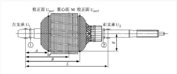
(1) left bearing baffle ring (2) right bearing baffle ring
FIG. 1 setting of rotor structure, support surface and correction surface
1. Degree of imbalance
2. Unbalance
Calculate the allowable unbalance magnitude Uper, where the unbalance intensity Su can be checked according to GB/T9239 / ISO1940.
3. Allow the distribution of the remaining balance
The work of allowable unbalance Uper assigned to the two straightening surfaces Uper1 and Uper2 is critical. The allowable unbalance of the distributed rotor is closely related to the structure (shape, center of gravity) of the rotor, the support surface and the setting of the straightening surface.
Distribution principle: the sum of the allowed unbalance of the two surfaces must be less than or equal to the total allowed unbalance Uper.
The rotor is asymmetric between the center of gravity and the two supporting surfaces, so the dynamic loads of the left and right supporting surfaces are:
In order to ensure that the dynamic load of the two supporting surfaces is not overloaded, the allowable unbalance of the two correction surfaces, Uper1 and Uper2, must also meet the constraint conditions of equations (6) and (7) :
According to the constraint equation of equations (4) ~ (7), it can be concluded that the values of allowed unbalance of the two correction surfaces are not unique.This can be directly reflected by the graphical method, which can be used to find the value range of the allowable unbalance of Uper1 and Uper2 of the two-school frontal distribution.
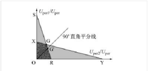
FIG. 2. Allowable unbalance of two correction planes by graphic method
Any point within the OXGR quadrilateral satisfies the constraints of equations (6) and (7).Therefore, the solutions of the two calibration surfaces are not unique. If G point is taken, both the right and left positive Uper1 and Uper2 can achieve their permitted unbalance simultaneously, but at this time, the unequality between the right and left supporting surfaces, U1 and U2, is not conducive to mass production, and the dynamic loads of the right and left supporting surfaces, U1 and U2, will also appear in the adverse phase.According to practical experience, take the bisector of the rectangular coordinate and the intersection point G 'of the quadrangle of OXGR, and at this time, the Uper1 = Uper2.The dynamic loads of U1 and U2 may differ slightly from their allowable values.
For the rotor structure shown in FIG. 1, the allowable unbalance of the two correction surfaces is distributed according to a certain proportion, set Uper1 / Uper2 = D, then D can be calculated according to equation (14) :
In the actual operation process, in order to facilitate personnel operation, the allowable unbalance between the two calibration surfaces of the motor was transformed into a Uper1 and a Uper2, which were divided by the counterweight position radius R of the two calibration surfaces of the motor rotor respectively. Finally, the actual allowable unbalance between the two calibration surfaces of the motor rotor was obtained.Uper2 '= Uper2 / R.
4. Balance correction
Using zhuoxuanjin horizontal soft support dynamic balancing machine detection.At the end of each test, the dynamic balancing machine automatically separates the initial unbalance or residual unbalance on the two correction surfaces.If the initial unbalance or residual unbalance of the two correction surfaces exceeds the set allowable unbalance, the dynamic balancing machine will alarm.Operators according to the dynamic balance machine shows that both the initial unbalance correction surface or residual unbalance and difference between the value and phase, will right amount balance on the surface of the cement paste in two correction respectively corresponding position, and then to detect, aggravating (including reducing last too much weight), until the rotor balance qualified.Balanced cement on the front of the rotor school (paste cement position) has a certain requirement, the adhesive surface should be dry without oil, need to wipe with alcohol.Balance cement mixture preparation, such as the volume of party a and component b cement mix, low temperature in winter conditions, cement can be preheated (25 ~ 30 ℃ or so) soft after use.The hybrid method is simple and effective.
5. Precautions
The rotor initial unbalance should not be too large.For the rotor with large initial unbalance, although it can be balanced to the allowable unbalance range through correction, the increase of the entire mass (weight) of the rotor is also relatively large, which will affect the motor's operating accuracy (such as the accuracy of reset, etc.).Therefore, attention should be paid to the manufacturing accuracy of the rotor parts and the rotor itself (such as the straightness of the rotor spindle, the coaxiality of the core and commutator, the equisection of the cogs, the evenness of the rotor coil arrangement, and the opening of the bearing baffle ring should be installed in the opposite position as far as possible).Make sure it's symmetric!
(1) the prerequisite of on-site dynamic balance is the judgment of unbalanced fault, the determination of the number of balancing faces and the completion of various preparatory work.If the equipment has been shut down, replace the reflector.
(2) check whether the function of balancing instrument and power supply are sufficient and the connection status of cable lines.
(3) vibration sensor and photoelectric sensor should always be installed in the same position.
(4) input the original record, test weight record and test weight block data into the calculator accurately.Each data recording shall be accurate, and the vibration amplitude and phase after the first trial weight shall be compared with the original record. If the change is not large and does not reach more than 20%, it indicates that the trial weight is inappropriate, and its size and position shall be reconsidered.
(5) before starting the equipment, please contact the field operator in a timely manner, and the equipment can only be started after confirmation.
(6) in the process of all on-site balancing work, attention shall be paid to and observe the running state of the equipment at all times. If abnormal phenomena are found in the equipment, the machine shall be immediately stopped to protect personal and equipment safety.